In this post we will touch upon the calibration component for multi-touch systems. By the end of this post we will implement a calibration widget that is integrated with our tracker modules, but before we do that we'll discuss the mathematics behind one method for mapping camera space to screen space. Below is a screen capture of our calibration widget awaiting input.
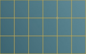
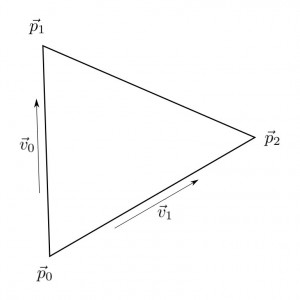
Our calibration implementation will divide each quad in the above image into two triangles, an upper left and a lower right triangle. For each point in screen space there exists a corresponding point in camera space, and our job is to map a triangle in camera space to one in screen space. In the diagram below we have an arbitrary triangle. We can define two basis vectors, \(\vec v_0\) and \(\vec v_1\), in \(\mathbb{R}^{2}\) by selecting two sides of our triangle,
\begin{align}
\vec v_0 &= \vec p_1 - \vec p_0\\
\vec v_1 &= \vec p_2 - \vec p_0
\end{align}
Any point in \(\mathbb{R}^{2}\) can then be written as a linear combination of \(\vec v_0\) and \(\vec v_1\).
\begin{align}
\vec p &= s \vec v_0 + t \vec v_1
\end{align}
If we let \(\vec p_0\) be the zero vector, then \(\vec p\) lies inside the triangle precisely when all of the following hold,
\begin{align}
s &\ge 0\\
t &\ge 0\\
s + t &\le 1
\end{align}
We thus have a coordinate, \((s,t)\), that we can use to map into screen space. If our test point belongs to the upper left triangle of the third quad in and second down, our screen space coordinates would be,
\begin{align}
s_x &= (3-1+s)\Delta x\\
s_y &= (2-1+t)\Delta y
\end{align}
Where \(\Delta x\) and \(\Delta y\) are defined to be,
\begin{align}
\Delta x &= \frac{w}{a-1}\\
\Delta y &= \frac{h}{b-1}
\end{align}
with \(w\) and \(h\) representing the width and height of our screen and \(a\) and \(b\) representing the number of horizontal and vertical calibration points, respectively.
So given a point, \(\vec p\), we need to calculate \(s\) and \(t\). We can use the vectors, \(\vec v_0\) and \(\vec v_1\), to give us the system,
\begin{align}
\vec p \cdot \vec v_0 &= s \vec v_0 \cdot \vec v_0 + t \vec v_1 \cdot \vec v_0\\
\vec p \cdot \vec v_1 &= s \vec v_0 \cdot \vec v_1 + t \vec v_1 \cdot \vec v_1
\end{align}
Evaluating this system for \(s\) and \(t\) we have,
\begin{align}
s &= \frac{(\vec p \cdot \vec v_0)(\vec v_1 \cdot \vec v_1)-(\vec p \cdot \vec v_1)(\vec v_0 \cdot \vec v_1)}{(\vec v_0 \cdot \vec v_0)(\vec v_1 \cdot \vec v_1)-(\vec v_0 \cdot \vec v_1)^2}\\
t &= \frac{(\vec p \cdot \vec v_1)(\vec v_0 \cdot \vec v_0)-(\vec p \cdot \vec v_0)(\vec v_0 \cdot \vec v_1)}{(\vec v_0 \cdot \vec v_0)(\vec v_1 \cdot \vec v_1)-(\vec v_0 \cdot \vec v_1)^2}
\end{align}
The process for implementing a calibration system boils down to three steps:
- Accept calibration points via the calibration widget.
- Notify our tracker modules of the calibration data once the data set has been received.
- Map the detected blobs from camera space to screen space.
We will first discuss the calibration widget. We will utilize the cTexture widget as a base class so we can supply an image such as the grid displayed in the first image of this post. The constructor of cCalibration accepts this image, a reference to our two blob trackers, and the number of horizontal and vertical calibration points. The reset() method allows us to undergo the calibration process again and isCalibrated() allows us to query if our system has been calibrated.
class cCalibration : public cTexture {
  private:
	point *calibration_points;
	int count;
	cTracker *tracker;
	cTracker2 *tracker2;
	int h_points, v_points;
	bool calibrated;

  protected:

  public:
	cCalibration(std::string filename, cTracker& tracker, cTracker2& tracker2, int h_points, int v_points);
	~cCalibration();

	void reset();
	bool isCalibrated();

	virtual void update();
	virtual void render();
};
In the definition below we will store our calibration points in the calibration_points property which will be passed to each of our trackers once all points have been received. Our update() method accepts one BLOB_DOWN event and stores the location in the calibration_points property. Additionally, if all points have been received, the trackers are updated with the calibration data set. Our render() method simply renders our background image and a circle designating the next input.
cCalibration::cCalibration(std::string filename, cTracker& tracker, cTracker2& tracker2, int h_points, int v_points) :
	cTexture(filename, point(0.0, 0.0), 0.0, 1.0), count(0), tracker(&tracker), tracker2(&tracker2), calibration_points(NULL), h_points(h_points), v_points(v_points), calibrated(false) {
	translate += dimensions/2;
	calibration_points = new point[h_points * v_points];
}

cCalibration::~cCalibration() {
	if (calibration_points) delete [] calibration_points;
}

bool cCalibration::isCalibrated() {
	return calibrated;
}

void cCalibration::reset() {
	bringForward();
	count = 0; calibrated = false;
}

void cCalibration::update() {
	if (calibrated) return;
	if (events.size() == 1 && events[0]->event == BLOB_DOWN) {
		calibration_points[count++] = events[0]->location;
	}
	if (count == h_points * v_points) {
		calibrated = true;
		tracker->updateCalibration(calibration_points, h_points, v_points);
		tracker2->updateCalibration(calibration_points, h_points, v_points);
	}
}

void cCalibration::render() {
	if (calibrated) return;
	glEnable(GL_TEXTURE_2D);
	glBindTexture(GL_TEXTURE_2D, texture);
	glColor4f(color.r, color.g, color.b, 1.0);
	glPushMatrix();
	glTranslatef(translate.x, translate.y, 0);
	glRotatef(rotate * 180 / M_PI, 0, 0, 1);
	glScalef(scale, scale, scale);
	glBegin(GL_QUADS);
	glTexCoord2f(0.0, 0.0); glVertex3f(-dimensions.x / 2, -dimensions.y / 2, 0.0);
	glTexCoord2f(0.0, 1.0); glVertex3f(-dimensions.x / 2,  dimensions.y / 2, 0.0);
	glTexCoord2f(1.0, 1.0); glVertex3f( dimensions.x / 2,  dimensions.y / 2, 0.0);
	glTexCoord2f(1.0, 0.0); glVertex3f( dimensions.x / 2, -dimensions.y / 2, 0.0);
	glEnd();
	int x = count % h_points, y = count / h_points;
	double x0 = dimensions.x / (h_points - 1) * x - dimensions.x / 2, y0 = dimensions.y / (v_points - 1) * y - dimensions.y / 2;
	//void renderCircle(float x, float y, float rad, int deg, GLfloat r, GLfloat g, GLfloat b);
	renderCircle(x0, y0, 16, 30, 1, 1, 1);
	glPopMatrix();
}
To our tracker objects we will add the following properties and methods:
	bool calibrated;
	point *calibration_points; int h_points, v_points;
	void resetCalibration();
	void updateCalibration(point* calibration_points, int h_points, int v_points);
	void applyCalibration();
The resetCalibration() method simply updates our calibrated flag.
void cTracker::resetCalibration() {
	calibrated = false;
}
The updateCalibration() method is called by our calibration widget and stores the number of horizontal and vertical calibration points in addition to the calibration data set itself.
void cTracker::updateCalibration(point* calibration_points, int h_points, int v_points) {
	calibrated = true;
	this->h_points = h_points; this->v_points = v_points;
	if (this->calibration_points) delete [] this->calibration_points;
	this->calibration_points = new point[h_points * v_points];
	for (int i = 0; i < h_points * v_points; i++) this->calibration_points[i] = calibration_points[i];
}
The applyCalibration() method is at the heart of our calibration system. It is responsible for mapping the blob locations from camera space to screen space. Again, this method could be optimized (e.g. using a look up table), but it does the job. For each blob detected, we cycle through each triangle in the calibration grid. If that blob exists within the current triangle, we update its location from camera space to screen space and proceed to the next blob.
void cTracker::applyCalibration() {
	if (!calibrated) return;

	int i, j, k;
	double s, t, v0v0, v1v1, v0v1, xv0, xv1, den;
	point p0, p1, p2, v0, v1, x, xp, trans;
	bool blob_found;
	double delta_x = (double)screen_width / (double)(h_points - 1), delta_y = (double)screen_height / (double)(v_points - 1);

	for (k = 0; k < blobs.size(); k++) {
		blob_found = false;
		for (j = 0; j < v_points - 1; j++) {
			for (i = 0; i < h_points - 1; i++) {
				// check both triangles with barycentric coordinates

				p0 = calibration_points[j * h_points + i];
				p1 = calibration_points[j * h_points + i + 1];
				p2 = calibration_points[(j + 1) * h_points + i];
				v0 = p1 - p0;
				v1 = p2 - p0;
				x = blobs[k].location - p0;
				xv0 = x.inner(v0);
				xv1 = x.inner(v1);
				v0v0 = v0.inner(v0);
				v1v1 = v1.inner(v1);
				v0v1 = v0.inner(v1);
				den = (v0v0 * v1v1 - v0v1 * v0v1);
				s = (xv0 * v1v1 - xv1 * v0v1) / den;
				t = (xv1 * v0v0 - xv0 * v0v1) / den;
				if (s >= 0 && t >= 0 && s + t <= 1) {
					// update blob
					xp = point((i + s) * delta_x, (j + t) * delta_y);
					trans = xp - blobs[k].location;
					blobs[k].location = blobs[k].origin = xp;
					blobs[k].min += trans; blobs[k].max += trans;
					blob_found = true; break;
				}

				p0 = calibration_points[(j + 1) * h_points + i + 1];
				p1 = calibration_points[(j + 1) * h_points + i];
				p2 = calibration_points[j * h_points + i + 1];
				v0 = p1 - p0;
				v1 = p2 - p0;
				x = blobs[k].location - p0;
				xv0 = x.inner(v0);
				xv1 = x.inner(v1);
				v0v0 = v0.inner(v0);
				v1v1 = v1.inner(v1);
				v0v1 = v0.inner(v1);
				den = (v0v0 * v1v1 - v0v1 * v0v1);
				s = (xv0 * v1v1 - xv1 * v0v1) / den;
				t = (xv1 * v0v0 - xv0 * v0v1) / den;
				if (s >= 0 && t >= 0 && s + t <= 1) {
					// update blob
					xp = point((i + (1 - s)) * delta_x, (j + (1 - t)) * delta_y);
					trans = xp - blobs[k].location;
					blobs[k].location = blobs[k].origin = xp;
					blobs[k].min += trans; blobs[k].max += trans;
					blob_found = true; break;
				}

			}
			if (blob_found) break;
		}
	}
}
That's about all there is to it. In our trackBlobs() method we call the applyCalibration() method after we have extracted the blobs in the current frame.
Eventually, I would like to implement a method for detecting reacTIVision fiducials, but my next post will likely discuss adding basic TUIO (Tangible User Interface Object) support by implementing a server module to parse OSC (Open Sound Control) packets. This will permit us to utilize the TUIOdroid application available for Android devices to control our application remotely. Furthermore, I would like to add a client module so our trackers can deliver blob events via the TUIO protocol.
Download this project: calibration.tar.bz2
